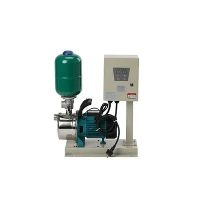
Hey there! I'm a supplier of Water Pump VFD Inverters, and today I'm gonna walk you through how to connect a water pump VFD inverter to a PLC. It might sound a bit technical, but don't worry, I'll break it down into easy - peasy steps.
Why Connect a Water Pump VFD Inverter to a PLC?
Before we get into the nitty - gritty of the connection process, let's quickly talk about why you'd want to do this. A Variable Frequency Drive (VFD) inverter for a water pump allows you to control the speed of the pump motor. This can save energy, reduce wear and tear on the pump, and provide better control over the water flow. A Programmable Logic Controller (PLC), on the other hand, is like a brain that can manage multiple processes and make decisions based on input signals. By connecting the VFD inverter to a PLC, you can automate the operation of the water pump. For example, you can set the PLC to adjust the pump speed based on the water level in a tank or the pressure in a pipeline.
What You'll Need
First things first, gather all the necessary tools and equipment. You'll need your water pump VFD inverter. We've got some great options, like the New Single - phase Water Pump Inverter and the 220V Water Pump Speed Drive Inverter. Check them out if you're in the market for a new one. You'll also need a PLC, some electrical wires, wire strippers, screwdrivers, and a multimeter to test the electrical connections.


Step 1: Read the Manuals
I know, reading manuals isn't the most exciting thing in the world, but it's super important. Both the VFD inverter and the PLC come with user manuals. These manuals will have detailed information about the electrical connections, programming settings, and safety precautions. Make sure you read them thoroughly before you start the installation. This will help you avoid making costly mistakes and keep you safe.
Step 2: Power Off Everything
Safety first! Before you start connecting any wires, turn off the power supply to both the VFD inverter and the PLC. This will prevent electrical shocks and damage to the equipment. Use a lock - out/tag - out procedure to make sure the power stays off while you're working.
Step 3: Identify the Connections on the VFD Inverter
The VFD inverter has several terminals for different types of connections. There are power input terminals, motor output terminals, and control terminals. The power input terminals are where you connect the incoming electrical power. The motor output terminals are connected to the water pump motor. The control terminals are used to connect the PLC. Usually, the control terminals include signals for start/stop, speed control, and feedback.
Step 4: Identify the Connections on the PLC
The PLC also has input and output terminals. The input terminals are used to receive signals from sensors or other devices. The output terminals are used to send control signals to the VFD inverter. You'll need to connect the appropriate output terminals of the PLC to the control terminals of the VFD inverter.
Step 5: Make the Electrical Connections
Now it's time to start connecting the wires. Use wire strippers to remove the insulation from the ends of the wires. Connect the appropriate wires from the PLC to the control terminals of the VFD inverter. Make sure the connections are tight and secure. You can use a screwdriver to tighten the terminal screws. Double - check the connections to make sure you haven't mixed up any wires.
Step 6: Grounding
Grounding is an important part of the electrical installation. Connect the grounding wires of both the VFD inverter and the PLC to a proper grounding point. This will help protect the equipment from electrical surges and reduce the risk of electrical shock.
Step 7: Power On and Test
Once you've made all the connections, turn on the power supply to the PLC and the VFD inverter. Use a multimeter to check the voltage and current at the connections. Make sure there are no short circuits or abnormal readings. If everything looks good, you can start testing the system. Use the PLC to send a start signal to the VFD inverter and see if the water pump starts running. You can also use the PLC to adjust the pump speed and check if the speed changes accordingly.
Step 8: Programming the PLC
After you've confirmed that the basic connection is working, you'll need to program the PLC. The programming will depend on your specific requirements. For example, you might want to set the PLC to start the pump when the water level in a tank drops below a certain level and stop the pump when the level reaches a maximum. You can use ladder logic or other programming languages supported by the PLC to create the control program.
Step 9: Troubleshooting
If you run into any problems during the installation or testing, don't panic. First, check the electrical connections to make sure they are correct. Then, refer to the manuals for troubleshooting tips. You can also contact our technical support team for assistance. We're always here to help you get your system up and running smoothly.
Step 10: Maintenance
Once the system is up and running, regular maintenance is key. Check the electrical connections periodically to make sure they are tight and free of corrosion. Clean the VFD inverter and the PLC to prevent dust and debris from accumulating. Follow the maintenance schedule recommended in the manuals.
In conclusion, connecting a water pump VFD inverter to a PLC can be a great way to automate the operation of your water pump system. It might seem a bit daunting at first, but if you follow these steps and take your time, you'll be able to do it successfully.
If you're interested in purchasing a high - quality water pump VFD inverter, check out our Water Pump Inverter range. We offer a wide variety of models to suit different applications and budgets. If you have any questions or need further assistance with the installation or programming, feel free to reach out. We're here to help you make the most of your water pump system.
References
- VFD Inverter User Manual
- PLC User Manual