Are there different wiring diagrams for different types of factory water pump switches? Well, let me tell you, as a factory water pump switch supplier, I've seen it all. And the answer is a big yes!
First off, let's talk about why there are different wiring diagrams. Different types of water pump switches have different functions and operating principles. For example, some switches are designed to control the pump based on pressure, while others might be triggered by flow rate or level. And each of these types requires a specific wiring setup to work properly.


Let's start with the pressure - based water pump switches. These are super common in factories. They turn the pump on when the water pressure drops below a certain level and turn it off when the pressure reaches a set maximum. The wiring for these switches usually involves connecting the power supply, the pump motor, and the pressure sensor. The power supply provides the electricity needed to run the whole system. The pump motor is what actually moves the water, and the pressure sensor is like the brain that tells the switch when to turn the pump on and off.
For a simple pressure - based water pump switch, the wiring might look something like this. You connect the live wire from the power supply to one terminal of the switch. Then, you connect the other terminal of the switch to the live wire of the pump motor. The neutral wire from the power supply is directly connected to the neutral wire of the pump motor. And don't forget to connect the pressure sensor to the appropriate terminals on the switch. This way, when the pressure changes, the sensor sends a signal to the switch, which then controls the power to the pump.
But here's the thing, not all pressure - based switches are the same. Some might have additional features like adjustable pressure settings or built - in overload protection. These extra features mean that the wiring diagram will be a bit more complex. For instance, if a switch has adjustable pressure settings, there will be additional wires or terminals that you need to connect to a control panel or a potentiometer. This allows you to set the exact pressure levels at which the pump turns on and off.
Now, let's look at flow - rate based water pump switches. These switches are used when you need to control the pump based on how much water is flowing through the system. The wiring for these switches is different because the main component is the flow sensor instead of the pressure sensor. The flow sensor measures the rate of water flow and sends a signal to the switch.
To wire a flow - rate based switch, you first connect the power supply to the switch just like with the pressure - based switch. Then, you connect the pump motor to the switch. But in addition, you need to connect the flow sensor to the switch. The flow sensor is usually installed in the water pipe, and it has wires that need to be connected to the appropriate terminals on the switch. This setup ensures that the pump only runs when there is a sufficient flow of water, which can be useful in preventing the pump from running dry.
Level - based water pump switches are another type. These are often used in tanks or reservoirs to control the water level. The wiring for level - based switches involves a level sensor, which can be a float switch or an ultrasonic sensor. The float switch rises and falls with the water level, and when it reaches a certain position, it triggers the switch. Ultrasonic sensors use sound waves to detect the water level.
When wiring a level - based switch, you connect the power supply, the pump motor, and the level sensor to the switch. The level sensor sends a signal to the switch based on the water level, and the switch then controls the pump. For example, if the water level in a tank gets too low, the switch will turn the pump on to fill the tank. Once the tank is full, the switch will turn the pump off.
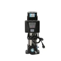
Now, I want to introduce some of our products. We have a Water Pump Pressure Controller with CE TUV Certificate. This controller is not only reliable but also meets international safety standards. It has a clear and easy - to - understand wiring diagram, making it suitable for both professional installers and DIY enthusiasts.
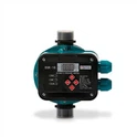
Another great product is our Wide Voltage Water Pump Controller. This controller can work with a wide range of voltages, which is really handy in different factory settings. The wiring for this controller is also designed to be as simple as possible, so you won't have to spend hours figuring it out.
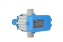
And if you're looking for a 110V option, we have the 110V Water Pump Electronic Pressure Switch. This switch is specifically designed for systems that run on 110V power. It offers precise pressure control and comes with a detailed wiring guide.
In conclusion, different types of factory water pump switches definitely have different wiring diagrams. It's important to understand the type of switch you're using and follow the correct wiring diagram to ensure the safe and efficient operation of your water pump system. Whether you're dealing with a pressure - based, flow - rate based, or level - based switch, make sure you know what you're doing.
If you're in the market for high - quality factory water pump switches and need help with the wiring or just want to discuss your specific requirements, don't hesitate to reach out. We're here to assist you and provide you with the best solutions for your water pump needs.
References:
- Electrical Installation Manuals for Water Pump Switches
- Technical Documents on Water Pump Control Systems